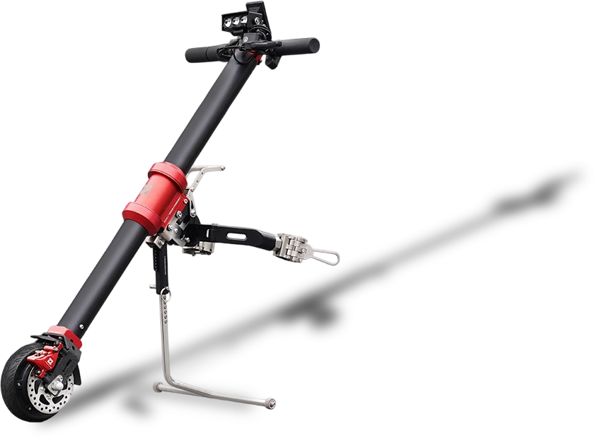
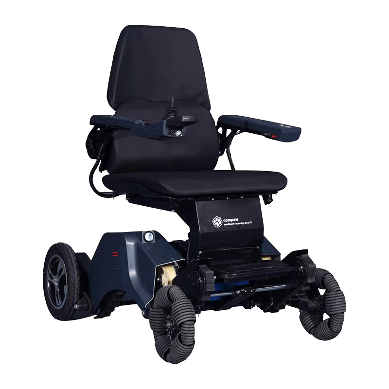
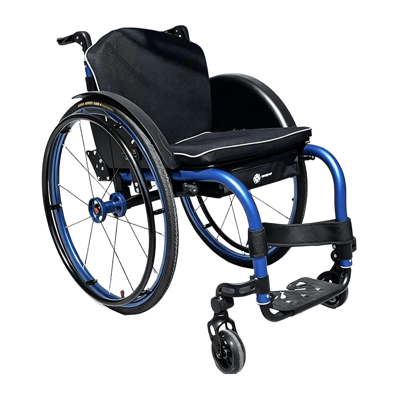
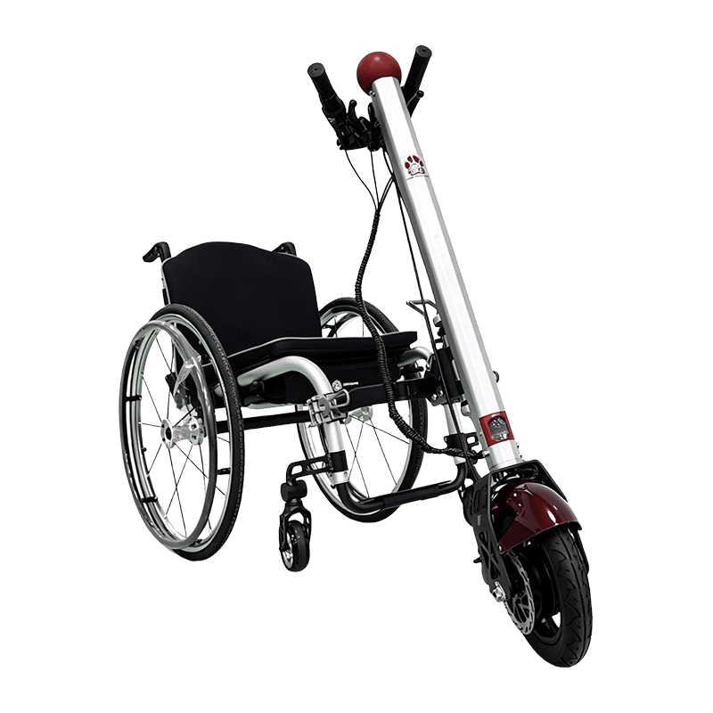
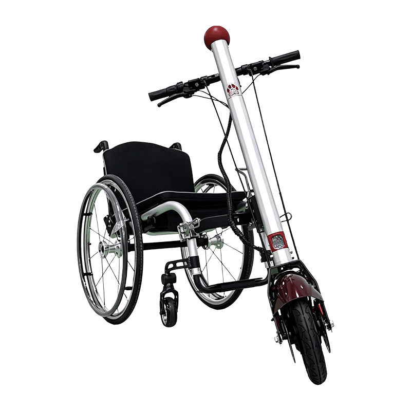
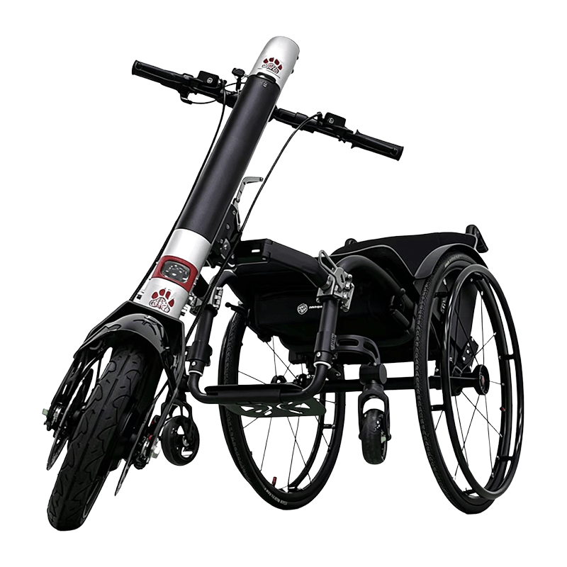
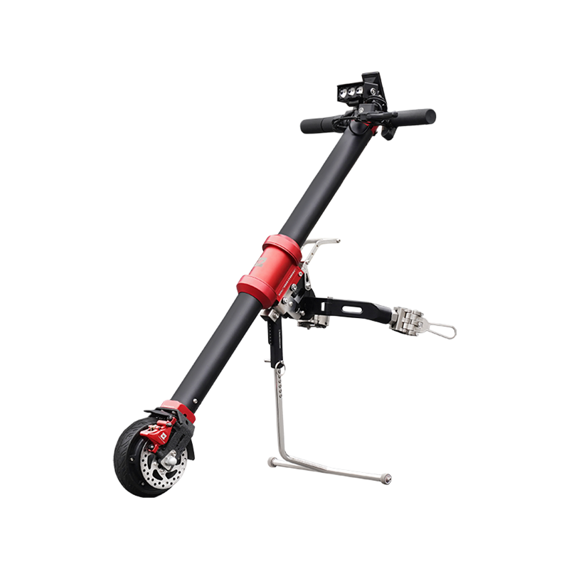
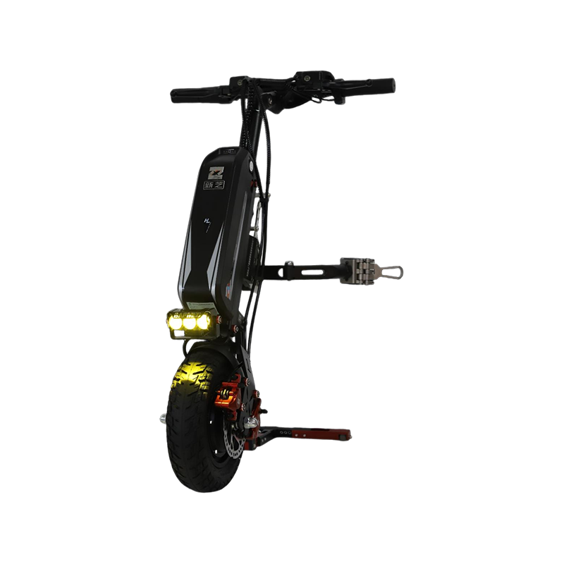
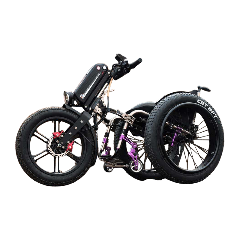
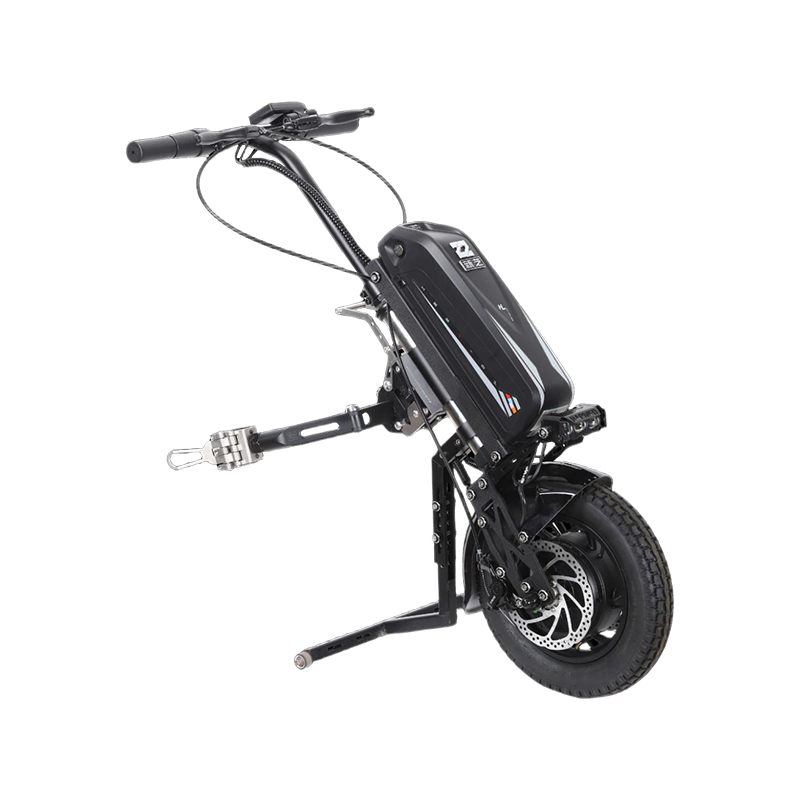
COMPAW manufactures the Electric Handcycle Wheelchair Attachment, Front-Mounted Powered Mobility Assist Device for Manual Wheelchairs — model KBCT03 — as a self-contained drive module that gives an existing manual wheelchair powered front-wheel propulsion. Our Suzhou factory produces the drive head, mounting mechanism, battery pack, handlebar control assembly and support frame as one integration-ready unit for wheelchair manufacturers, rehabilitation equipment distributors and OEM/ODM development teams.
The module electrifies a chair rather than replacing it. A 12-inch powered front wheel carries a 350W brushless motor, the chair frame stays as it is, and the rider keeps their own seating, rear wheels and transfer habits. What follows is the standard KBCT03 build, the configuration variables we adjust per project, and the project data we use to prepare a module specification and quotation.
How Front-Mounted Power Assist Works on a Manual Wheelchair
As a Wholesale Electric Handcycle Wheelchair Attachment, Front-Mounted Powered Mobility Assist Device for Manual Wheelchairs Suppliers, Exporter, Company, we match product configuration to the application, operating limits, interfaces and acceptance criteria defined for each project.
The KBCT03 connects to the front section of the wheelchair through a dedicated attachment mechanism and drives through the powered front wheel; the chair's own rear wheels are not motorised. Motor, battery and controller form an independent module, so the drive unit sits in front of the seat where the rider can steer it directly and where it can be isolated from the chair structure during service.
- Powered front wheel with 12-inch inner–outer pneumatic tyre
- 350W brushless silent motor with matched controller
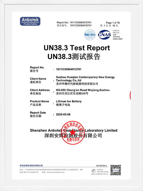
- 36V 8Ah lithium-ion rechargeable battery pack
- Foldable handlebar with touch-screen dashboard and battery level indicator
- Support frame and T-type pulley bracket transferring load into the chair frame
- Side connection or middle connection mounting, configured to the wheelchair geometry
KBCT03 Specifications and Their Working Limits
Every figure below is a rating and a configuration variable at the same time: when the drive unit is integrated into a customer's chair, we re-match it to the real load, terrain and target speed.
| Parameter |
Standard Value |
What It Governs |
| Battery |
36V 8Ah lithium-ion |
Travel distance and recharge cycle at the rated motor load |
| Motor |
350W brushless silent motor |
Continuous propulsion at rated speed, load and noise level |
| Endurance mileage |
25–30 km |
Range for the stated battery and motor combination |
| Tyre |
12-inch inner–outer pneumatic tyre |
Rolling comfort, pavement contact and small-obstacle behaviour |
| Gear |
3-speed electric speed change with reverse |
Low-speed manoeuvring, hill starts and backing out of tight spaces |
| Max. climbing angle |
26° |
Slope capability at the configured load and wheel diameter |
| Lighting |
Built-in headlight |
Visibility on low-light pedestrian routes |
| Connector |
Side connection / middle connection |
Mounting position across different wheelchair geometries |
| Support bracket |
T-type pulley bracket |
Load transfer between the drive unit and the chair frame |
| Brake system |
Dual-disc hydraulic brake |
Deceleration and holding on descents |
| Interface features |
Foldable handlebar, touch-screen dashboard, USB external charging, battery level indicator |
Rider control, status reading and device charging |
A 26° climb or the 25–30 km endurance figure is reached under a defined load, tyre pressure, slope length and surface. We confirm those conditions against the specific chair and rider weight instead of quoting the headline number on its own.
Configuration Options for OEM and ODM Programmes
Because the attachment ships as a module rather than a finished chair, most of the specification is open to project definition. We build the mounting structure to the wheelchair frame dimensions and mounting positions, and match the electrical side to the operating requirement.
- Drive parameters — motor output and battery capacity matched to total load, target speed, slope and daily distance
- Mounting structure — bracket geometry, side or middle connector position, and drive-wheel disengagement for chairs that must still be pushed manually
- Control layout — handlebar-mounted control unit, throttle response, speed limiting and dashboard features
- Wheel and brake — tyre specification and dual-disc hydraulic brake configuration
- Market adaptation — control language, technical documentation and certification sampling for the destination market
- Branding and packaging — OEM identification, packaging configuration and order volume planning
OEM/ODM work starts from the frame drawings and the operating target; we then issue a module specification covering drive, battery, control and mounting details for approval before tooling or batch production.
Application Fit
The KBCT03 suits projects where a manual wheelchair already exists and powered propulsion has to be added in front of it. Four recurring uses:
- Manual wheelchair electric conversion — conversion builders and mobility equipment suppliers adding powered propulsion to standard chairs.
- Rehabilitation mobility equipment — drive units integrated into assisted mobility equipment where powered propulsion is required.
- Accessible mobility environments — campuses, pedestrian routes, indoor facilities and other suitable paved areas, with real operating conditions set by complete-vehicle configuration, terrain and local regulations.
- Wheelchair manufacturing and OEM/ODM — a powered front-end option offered across an existing manual chair platform.
Mechanical Compatibility and Installation
Compatibility runs on frame geometry rather than brand. Before a batch is released we confirm the following against the customer's chair drawings or a sample chair.
- Available front mounting space and attachment-point dimensions
- Frame tubing dimensions and the mechanical fit of the mounting mechanism
- Front-wheel dimensions, ground clearance and the resulting change in overall centre of gravity
- Rated voltage and current compatibility between motor, controller and battery
- Drive-wheel disengagement where manual operation must remain available
- Installation and compatibility testing on the target wheelchair model before bulk production
Controls, Safety and Electrical Integration
The handlebar carries the control unit, touch-screen dashboard and battery level indicator, with USB external charging for the rider's own devices. A built-in headlight covers low-light routes, and the dual-disc hydraulic brake handles deceleration and holding on descents.
- Three electric speeds plus reverse for manoeuvring and backing out of tight spaces
- Independent motor, battery and controller module that can be isolated from the chair structure for service
- Cable routing and connector protection defined per mounting position during installation design
- Mobility equipment and electrical safety requirements verified per destination market
Quality Control, Acceptance and After-Sales Support
Production runs through full-process quality control under international manufacturing standards in our 50,000㎡ facility, supported by more than 300 staff and 100-ton production capacity. Acceptance is agreed per project: functional checks on motor, controller, battery and brake, plus installation and compatibility testing against the target wheelchair before bulk production.
- Multilingual technical documentation and online troubleshooting guides for channel partners
- Rapid spare parts supply through our attachment accessories line
- Remote fault diagnosis, operator training and on-site maintenance support for rehabilitation and care teams
- Localized certification adaptation for EU, North American and Middle East markets, completed together with the customer
Our Power Attachment Range and Where Each Model Fits
The KBCT03 front-mount is one option in our electric handcycle attachment range, produced by COMPAW as China Power Trike Wheelchair Attachment Manufacturers. Sibling units serve the same manual-wheelchair platform with different priorities.
- SlimTough — portable build for chairs that are folded and transported often: SlimTough portable power attachment
- NeoPath — all-terrain drive; OmniPath — off-road drive; Zepath — comfort-series drive; ProPath — professional specification
- Supporting hardware — electric handcycle attachment accessories for mounting, battery and control spares
Information We Use to Configure Your Solution
| Project Input |
What It Determines |
| Wheelchair frame drawings or key dimensions: tube diameter, front clearance, attachment points |
Mounting mechanism geometry and connector position |
| Complete-vehicle weight and maximum occupant load |
Motor output, braking requirement and safe climbing angle |
| Target speed and operating terrain |
Gear range, tyre specification and controller settings |
| Required travel distance and daily operating time |
Battery capacity at the rated voltage |
| Mounting position: side or middle connection |
Bracket geometry and cable routing |
| Whether manual operation must be retained |
Drive-wheel disengagement mechanism |
| Control requirements: dashboard, throttle, speed limiting |
Handlebar control assembly and interface features |
| Target market and regulatory route |
Electrical safety and mobility equipment compliance work |
| Estimated order quantity and delivery schedule |
Tooling, batch planning and packaging configuration |
Common Project Questions
Which manual wheelchairs accept the KBCT03 attachment?
Compatibility depends on frame structure, front clearance, frame tubing dimensions, attachment points and overall geometry. We ask for the wheelchair model information and key mounting dimensions, then confirm fit on drawings or a sample chair before a batch is planned.
Can the chair still be operated manually once the attachment is fitted?
That depends on the mechanical configuration chosen for the project. Where manual push operation must remain available, we design the drive-wheel disengagement mechanism and attachment structure around that requirement during the selection stage rather than after production.
How do you size motor output and battery capacity?
Motor output is selected from total wheelchair and occupant load, target speed, slope, wheel diameter, terrain and continuous operating time — not from chair dimensions alone. Battery capacity follows the rated voltage, motor power, required travel distance, total load and operating time, and we can specify different packs for different markets and duty cycles.
What is verified before shipment?
Each unit passes functional checks on motor, controller, battery, lighting and dual-disc hydraulic brake, together with rated voltage and current compatibility across the electrical set. For new chair platforms we complete installation and compatibility testing on the target model before bulk production, and the results are documented for the customer's acceptance record.
Does the 26° climbing angle and 25–30 km range apply to every chair?
No — both are tied to the configured motor, battery, total load, tyre pressure and surface. We confirm the realistic climbing angle and range for the actual chair and rider weight, and state those figures in the approved module specification.

 English
 русский
 Español
 Deutsch